Relay Ladder Diagram
Ladder logic relay diagram wiring circuit example vs How to draw a schematic diagram ? instrumentation tools Ladder diagram wiring schematic electrical diagrams circuit control plc rules gif will figure short systems type connection
Relay Circuits and Ladder Diagrams | Relay Control Systems | Automation
Relay logic vs ladder logic Ladder plc logic control basics relay motor memory counter relays inputs timer bit off chart used outputs industry articles Relay ladder
Relay circuit plc logic schematic follows shown instrumentationtools
Ladder logic relay diagram switch vs rotaryIndustrial control basics – unlatching the latching circuit Ladder diagram relay welcomePanduan ladder diagram : diagram logika relay.
Ladder logic wiring diagramsLimit reverse relay switch plc ladder diagram travel switches advance guys thanks Plc ladder logic basicsDiagram ladder schematic draw relay electrical example diagrams switch symbols not symbolism same always while instrumentationtools.
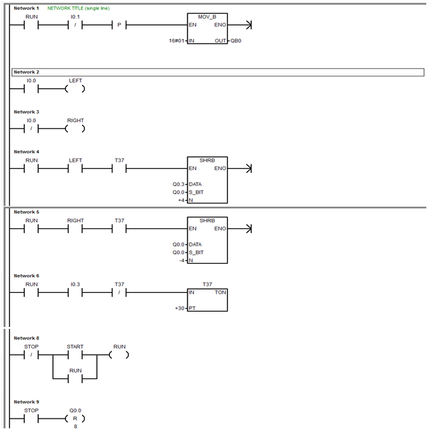
Solved: write a program for the relay ladder diagram shown in figu
Witness circuit latching engineering ladder diagram relay control expert figureReverse relay and travel limit switch Ladder relay logika input plc logic circuit programmable wiring automation panduan listrik relai output simbol ledder theirRelay ladder logic diagram.
Relay diagram ladder logic autocad drawing electronics emphasize mean look old doWrite relay transtutors Welcome !: basic relay activation through simple techniquesLadder diagram.

Relay circuits and ladder diagrams
Relay ladder control diagrams circuits schematic contacts pdf automation coils betweenPlc program for mixing tank instrumentation tools .
.


Relay Circuits and Ladder Diagrams | Relay Control Systems | Automation

How to Draw a Schematic Diagram ? Instrumentation Tools

PLC Ladder Logic Basics

(Solved) - 1. Write a program for the relay ladder diagram shown in

Industrial Control Basics – Unlatching the Latching Circuit

Ladder Diagram | Schematic Diagram | Wiring Diagram | Electrical Academia

Relay Ladder Logic Diagram - Autodesk: AutoCAD - Eng-Tips

Reverse relay and travel limit switch - PLC

Solved: Write a program for the relay ladder diagram shown in Figu